MATEK MATEKSYS AP_PERIPH CAN NODE CAN-G474
MATEK MATEKSYS AP_PERIPH CAN NODE CAN-G474
Обычная цена
$15.22 USD
Обычная цена
$0.00 USD
Цена со скидкой
$15.22 USD
В наличии: 399
Количество
Не удалось загрузить сведения о доступности самовывоза
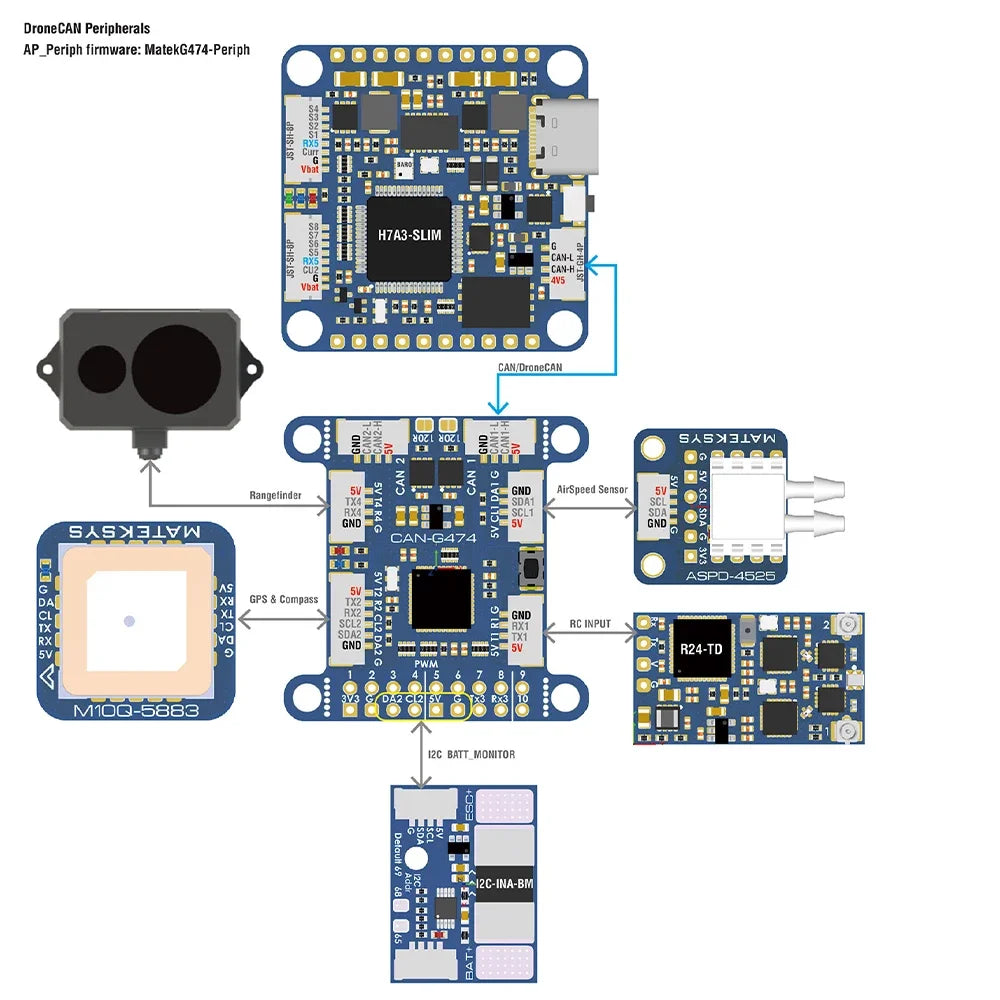
MATEK MATEKSYS AP_PERIPH CAN NODE CAN-G474 With AP_Periph, CAN Node, DroneCAN, G474, FDCAN 5Mbit/s for RC FPV Drone
support GNSS, Compass, Barometer sensors over MSP protocol. MSP is enable on TX3 by default.
SPI pads for RM3100 are on bottom side, with "CS, MOSI, MISO, SCK" silkprint
PWM1-10 on DuPont 2.54mm holes
PWM11 pad is on bottom side, with "11" silkprint
Blue, Slow blinking, communicating with flight controller
Red, 3.3V indicator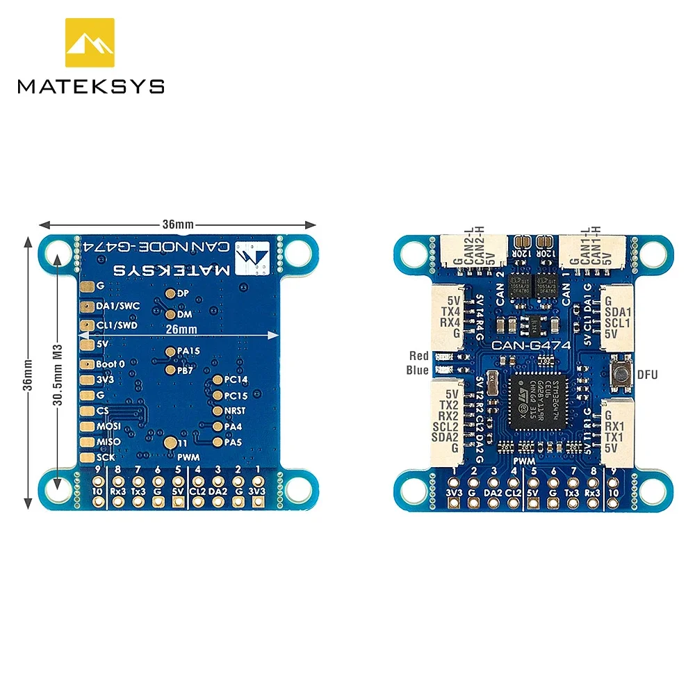

CAN Node parameters
Просмотреть всю информацию
- CAN-G474 is an Adapter Node based on ArudPilot AP_Periph firmware.
- with 5Mbit/s CAN transceiver and STM32G474 MCU, CAN-G474 is capable of CANFD.
- With this board, you can easily utilize the ArduPilot driver library to convert ArduPilot supported GNSS, Compass, Barometer, Airspeed sensor, Rangefinder, Proximity sensor, Electronic Fuel Injectors and GPIO based (PWM, LED notify) peripherals to DroneCAN bus peripherals.
- MCU: STM32G474CE, 512KB Flash
- CAN transceiver data rates up to 5Mbit/s
- 2x CAN bus
- 4x UARTs
support GNSS, Compass, Barometer sensors over MSP protocol. MSP is enable on TX3 by default.
- 2x I2C bus
- 1x SPI
SPI pads for RM3100 are on bottom side, with "CS, MOSI, MISO, SCK" silkprint
- 11x PWM outputs
PWM1-10 on DuPont 2.54mm holes
PWM11 pad is on bottom side, with "11" silkprint
- ST debug, SWC & SWD(on bottom side)
- UART1(TX1,RX1) support firmware update in DFU mode
- LED
Blue, Slow blinking, communicating with flight controller
Red, 3.3V indicator
- Input voltage range: 4.5~5.5V @5V pad/pin
- Power consumption: 62mA
- Operating Temperatures: -30~85 °C
- 5x JST-GH-4P(SM04B-GHS-TB) for CAN1, CAN2, I2C1, UART1 and UART4
- 1x JST-GH-6P(SM06B-GHS-TB) for UART3+I2C2
- 18x DuPont 2.54mm holes
- Board Size: 36mm*36mm*6mm. 5.2g,
- Mounting: 30.5mm 4x Dia.3mm
- 3D file : CAN-G474_STEP.zip
- 1x CAN-G474 board
- 2x JST-GH-4P to JST-GH-4P 20cm silicon wire
- 1x JST-GH-6P to JST-GH-6P 20cm silicon wire
- ArduPilot AP_Periph MatekG474-Periph for peripheral sensors
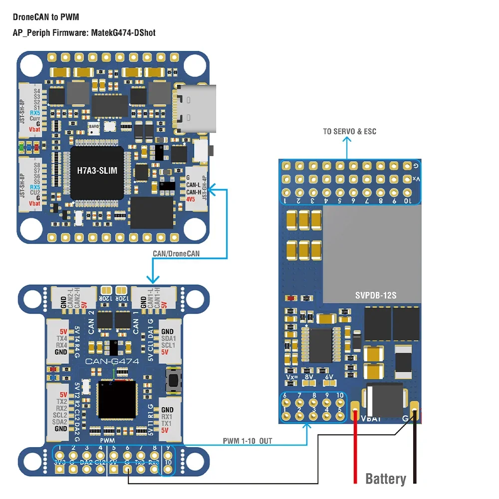
- ArduPilot AP_Periph MatekG474-DShot for DroneCAN-PWM output
- Update via DroneCAN GUI Tool or Mission Planner–DroneCAN Tab, load "AP_Periph.bin"
- Update via STM32CubeProgrammer in DFU mode, connect USB-TTL module to UART1, Plug USB while holding the DFU button in, load "AP_Periph_with_bl.hex".
- Just need to connect either one CAN bus to flight controller, or connect both to FC for redundancy.
- SWC/SWD share MCU pins with SDA1/SCL1
- Other MCU pins not specified are useless for now.
- CAN-G474 support 1Mbit ~ 5Mbit CAN/CANFD, CAN-L431 works with 1Mbit CAN.
CAN Node parameters

Flight controller Parameters for sensors
- CAN_D*_PROTOCOL = 1
- CAN_P*_DRIVER = 1
- GPS*_TYPE = 9 DroneCAN
- COMPASS_TYPEMASK = 0 (DroneCAN Unchecked)
- ARSPD*_TYPE = 8 (DroneCAN)
- BATT*_MONITOR = 8 (DroneCAN)
- RNGFND*_TYPE = 24 (DroneCAN)
- EFI*_TYPE = 5 (DroneCAN)
- PRX*_TYPE = 14 (DroneCAN)
Flight controller Parameters for PWM
- CAN_D*_PROTOCOL = 1
- CAN_P*_DRIVER = 1
- CAN_D*_UC_ESC_OF = 4 (Plane 4.2.1 or newer)
- CAN_D*_UC_ESC_BM = x
- CAN_D*_UC_SRV_BM = x
- BRD_SAFETYENABLE = 0 (if your flight controller doesn't have safety pin)
- Tutorial : Using MatekL431 adapters for PWM and DShot